Outboard (or “warm”) window installation places the window unit in the insulation plane, not deep inside the structural wall. The objective is clear: minimize thermal bridges, keep interior surfaces warm, and make airtightness more reliable—especially for Passive House-level envelopes.
From the project video: this is modern architecture built with non-removable formwork (ICF-style) using Passive House block. Materials are selected for maximum energy efficiency. Glazing uses VEKA Softline 70 profiles, with RC2 burglary-resistant window class.
https://youtu.be/qHodgUjohWI?si=tksvksen2PFa6vK4
Why mount windows in the insulation layer
The wall–window junction is one of the most sensitive areas in any energy-efficient building. If the frame sits in a thermally weak position (cold reveal, uninsulated sill, discontinuous insulation), the result is a linear thermal bridge that increases heat loss and can reduce comfort near glazing.
Better comfort and more predictable airtightness detailing
Cleaner integration with thick insulation and modern façade systems
Design intent
Treat the window as part of the thermal envelope: insulation overlaps the frame; brackets carry loads back to structure with minimal bridging.
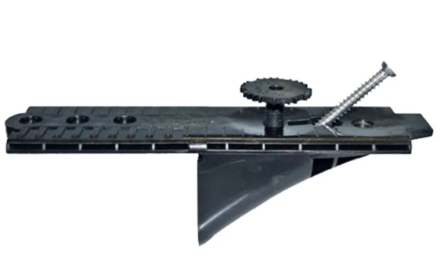
How loads are transferred (brackets / consoles)
Moving the window outward requires a clear load path. The unit’s weight, wind pressure/suction and operational loads must transfer into the structural wall. This is typically achieved with engineered brackets/consoles suited for outboard installation.
Brackets set geometry: plane, alignment, installation gap.
Fixings resist loads: transfer forces to the concrete/masonry/timber core.
Thermal bridging is managed: optimized bracket layout and compatible reveal insulation.
The 4 critical layers to keep continuous
1) Structure (load-bearing line)
Brackets must anchor into structure. Never rely on insulation or exterior render for load transfer.
2) Airtightness (interior line)
Use interior airtight tapes/membranes from frame to the wall airtight layer. Corners must be continuous and stress-free.
3) Thermal insulation (warm wrap)
Return insulation into the reveal to overlap the frame (within system limits) and reduce junction heat loss.
4) Weather & water control (exterior line)
Exterior sealing must shed rain outward. Use correct laps, head flashing, and a sill detail that cannot trap water.