
Outboard (or “warm”] window installation places the window unit in the insulation plane, not deep inside the structural wall. The objective is clear: minimize thermal bridges, keep interior surfaces warm, e make airtightness more reliable—especially para Passive House-level envelopes.

From the project video: this is modern architecture built with non-removable formwork (ICF-style] using Passive House block. Materials are selected for maximum energy efficiency. Glazing uses VEKA Softline 70 profiles, with RC2 burglary-resistant window class.

https://youtu.be/qHodgUjohWI?si=tksvksen2PFa6vK4

Why mount windows em the insulation layer

The wall–window junction is one of the most sensitive areas em any energy-efficient building. If the frame sits em a thermally weak position (cold reveal, uninsulated sill, discontinuous insulation], the result is a linear thermal bridge that increases heat loss e can reduce comfort near glazing.

  • Lower junction heat loss by improving Ψ (psi]
  • Higher interior frame temperatures (lower condensation risk]
  • Better comfort e more predictable airtightness detailing
  • Cleaner integration com thick insulation e modern façade systems
Design intent

Treat the window as part of the thermal envelope: insulation overlaps the frame; brackets carry loads back a structure com minimal bridging.

How loads are transferred (brackets / consoles]

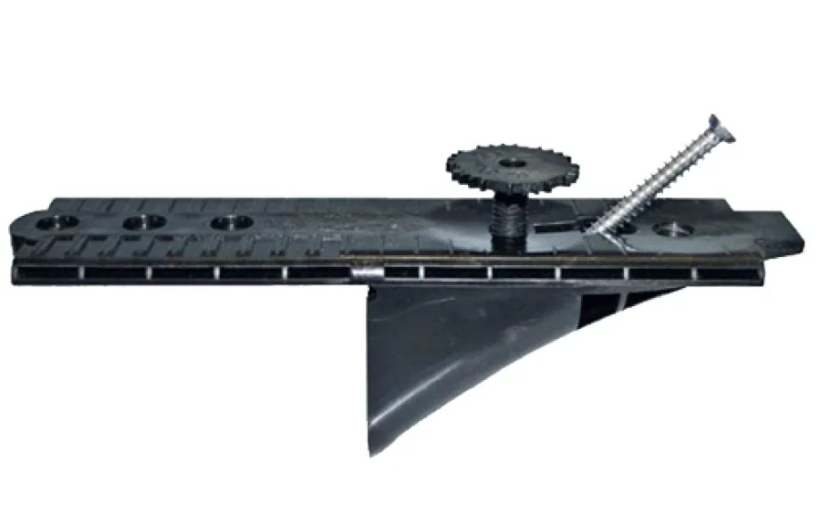
Moving the window outward requires a clear load path. The unit’s weight, wind pressure/suction and operational loads must transfer into the structural wall. This is typically achieved with engineered brackets/consoles suited for outboard installation.

  • Brackets set geometry: plane, alignment, installation gap.
  • Fixings resist loads: transfer forces a the concrete/masonry/timber core.
  • Thermal bridging is managed: optimized bracket layout e compatible reveal insulation.

The 4 critical layers a keep continuous

1] Structure (load-bearing line]

Brackets must anchor into structure. Never rely on insulation ou exterior render para load transfer.

2] Airtightness (interior line]

Use interior airtight tapes/membranes de frame a the wall airtight layer. Corners must be continuous e stress-free.

3] Thermal insulation (warm wrap]

Return insulation into the reveal a overlap the frame (within system limits] e reduce junction heat loss.

4] Weather e water control (exterior line]

Exterior sealing must shed rain outward. Use correct laps, head flashing, e a sill detail that cannot trap water.

Recommended installation sequence

  1. Check openings: dimensions, squareness, anchor zones.
  2. Install brackets: align e tighten a spec; verify spacing.
  3. Place e level windows: packers at load points; check operation.
  4. Finalize mechanical fixings: re-check diagonals e sash clearance.
  5. Insulate the gap: low-expansion foam ou mineral wool; no voids.
  6. Interior airtight tape: continuous e well-adhered; primer if required.
  7. Exterior weather layer: tapes/membranes + flashings; drainage at sill.
  8. Reveal insulation: achieve designed overlap e protect edges.
  9. QA photos: document antes de finishes; prep para blower-door testing.

Common mistakes

  • No junction detail → random reveal geometry and higher thermal bridging.
  • Bracket layout not verified → movement, cracks, leaks.
  • Discontinuous airtight tape → blower-door failures around frames.
  • Wrong layer logic → exterior tapes used as airtight layer without protection.
  • No sill water strategy → trapped water and durability issues.

QA checklist

  • Opening dimensions/substrate verified e recorded
  • Bracket type/spacing matches loads e manufacturer guidance
  • Window plumb/level/diagonals checked; sashes operate correctly
  • Packers only at load points
  • Gap insulation installed without voids
  • Interior airtight tape continuous e well-adhered
  • Exterior weather line continuous e correctly lapped
  • Reveal insulation achieves designed frame overlap
  • Photo documentation antes de finishes